vic 20 info
Exploring the Control Port
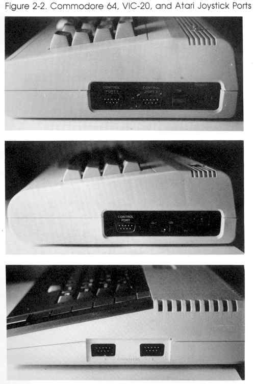
With a basic understanding of how a computer operates, you can now begin exploring the computer's ports, the gateways through which information flows into and out of your computer. The ports are often referred to as I/O ports, which stands for input/output ports. Though there are several different 1/O ports on your computer, the projects in this book use one port in particular, the joystick port.
The joystick port provides plenty of access to your computer for our demonstation circuits. Connectors for this port are also commonly available. They are the same type as those found on joysticks and game paddles-D-subminiature female connectors.
The joystick port has nine pins. Pins 1, 2, 3, 4, and 6 are I/O pins. They are connected to wires which may be used to communicate binary (on/off) data. Pins 5 and 9 are used to input analog data-we'll learn more about these pins later in the book. Pin 7 is connected to a +5-volt source, while pin 8 is connected to the power supply ground.
Once you can identify the pins of a control port, your next step is to understand how they can be used. A few homemade "tools" will help.
A Simple Logic Probe
A logic probe is a device that lets you "look" into what's going on in a digital circuit. It's a device that tells you whether a 1 (high state) or a 0 (low state) is present at a point in the circuit. A simple logic probe can be assembled from two main components. This logic probe can be used to see how the I/O lines of the control port are used to input information.
To construct the logic probe, you'll need these parts:
(In this book, all part numbers are Radio Shack part numbers.)
With a basic understanding of how a computer operates, you can now begin exploring the computer's ports, the gateways through which information flows into and out of your computer. The ports are often referred to as I/O ports, which stands for input/output ports. Though there are several different 1/O ports on your computer, the projects in this book use one port in particular, the joystick port.
The joystick port provides plenty of access to your computer for our demonstation circuits. Connectors for this port are also commonly available. They are the same type as those found on joysticks and game paddles-D-subminiature female connectors.
| Control Port 1 | Control Port 2 (Commodore 64) | ||
| Pin | Type | Pin | Type |
| 1 | JOYA0 | 1 | JOYB0 |
| 2 | JOYA1 | 2 | JOYB1 |
| 3 | JOYA2 | 3 | JOYB2 |
| 4 | JOYA3 | 4 | JOYB3 |
| 5 | POT AY | 5 | POT BY |
| 6 | Button A/LP | 6 | Button B |
| 7 | +5 volts | 7 | +5 volts |
| 8 | Ground | 8 | Ground |
| 9 | POT AX | 9 | POT BX |
The joystick port has nine pins. Pins 1, 2, 3, 4, and 6 are I/O pins. They are connected to wires which may be used to communicate binary (on/off) data. Pins 5 and 9 are used to input analog data-we'll learn more about these pins later in the book. Pin 7 is connected to a +5-volt source, while pin 8 is connected to the power supply ground.
Once you can identify the pins of a control port, your next step is to understand how they can be used. A few homemade "tools" will help.
A Simple Logic Probe
A logic probe is a device that lets you "look" into what's going on in a digital circuit. It's a device that tells you whether a 1 (high state) or a 0 (low state) is present at a point in the circuit. A simple logic probe can be assembled from two main components. This logic probe can be used to see how the I/O lines of the control port are used to input information.
To construct the logic probe, you'll need these parts:
| Quantity | Part | Part Number |
| 1 | Light-emitting diode (LED) | 276-041 |
| 1 | 1K ohm resistor | 271-8027 |
| 2 | Alligator clips | 270-378 |
| You'll also need some stranded copper wire (about #22 gauge-Radio Shack part number 278-1307) to make the probe leads, as well as some electrical insulation tape. | ||
(In this book, all part numbers are Radio Shack part numbers.)
posted by tenka at 11:18 PM
0 comments
![]()
![]()
